With prototypes (read: breadboards with lots of dangle-y wires!) complete, I’m thinking about how to scale up the circuits.
Each archway will need a set of circuits to run the sensors and lighting. Each sepal has three archways, so we’re talking about nine (9) circuits. That’s just do-able by hand, but the risk of errors and variation between circuits is high. Fixing and maintaining circuits that have variation in-the-field is painful, and I speak from experience.
Each lighted triangle will need a set of circuits to run the lights. Each sepal has three “up” triangles and three “down” triangles, so six (6) of these circuits per sepal, or eighteen (18) for the whole project. Controlling for errors and variation at that scale isn’t possible.
Solution: get some printed circuit boards (PCB) fabricated. In our shop, we can mill boards (sort of: my Shapeoko 2/X-carve isn’t quite up for the level of runout control needed for fine work). However, OSHpark.com (run by John DeCristofaro near Portland, OR) provides a great (and fast!) custom PCB fabrication service. For the CAD work, I used EagleCAD. OSH Park lets you upload a board file (the physical representation of the circuit) directly, which saves a lot of time and hassle since you don’t have to produce CAM-ready (“Gerber”) files.
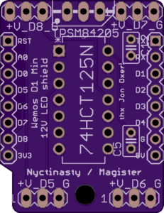
So, for the lighted triangles, we have this board:

It’s tiny: 1″ by 1.3″. It’s the same size as the Wemos Mini D1, which is shaking out to be the workhorse of the project. That machine runs at 120 MHz, has a built-in WiFi stack, and lots of support from the maker community. However, it uses 3.3v logic-level, and the 12V LEDs we use expect a 5V signal. To deal with that, we use a high-speed transceiver to convert 3.3V to 5V, and that’s the part right in the middle of the board (“75HCT125N”). Physically, the Wemos Mini will be ~1 cm above the circuit board, and the transceiver will be soldered to the board below it. Also, the LEDs run at 12V, so we use an all-in-one 12V to 5V step-down (“TPSM84205”) to power the Wemos Mini. Finally, at the top and bottom edges of board, there are connection points for 4x LED strips, but we plan to use only 2x LED strips.
In future revisions, I may expand the board to have a 12V connector so that I don’t need to have another method to connect power to the LED strips. At something like an 8 day turn-around, not a problem to revise.
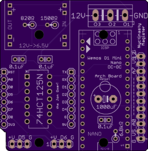
For each archway, we have this board:

This one is bigger: 2″ by 2″. You can see the same Wemos Mini D1 outline in the lower left, for scale. I only make two LED strip connectors available. The 12V power connection is in the upper right. In the upper-left, there’s an adjustable voltage regulator, stepping 12V down to 6.5V. That’s an odd voltage, but we found that the analog distance sensors provide more range than their specifications if overvolted. In the lower-right, there’s an Arduino Nano. Yeah, running two microcontrollers to get this done. We need eight (8) analog readings, and the Wemos can only handle one (1). So, the Nano is functioning as a (fancy) analog-to-digital converter. It’s also a 5V system, so we include some resistors (upper-left, under the voltage regulator) to convert to 3.3v for serial communication between the two microprocessors.
I’m pretty happy with this layout, but again, we may change things around after evaluating the circuit.
Once these arrive from fabrication (probably third week of January), it’s a matter of soldering parts into the board, following the directions on the board itself. This provides an opportunity for people working on the project to try their hand at soldering in a (fairly) risk-free and straight-forward context.
Peace,
Mike